

|
|
|
|
Contents: Principle of Operation, Hygienic Meters, In-Line Turbines
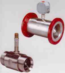
As fluid passes through the Turbine Flowmeter it causes the blades of a freely supported rotor, set at a prescribed angle to the direction of flow to produce a speed of rotation which is directly proportional to volumetric flow rate. A pick-up assembly, mounted on the outside of the flow meter body, detects the passage of each blade and generates a sinusoidal voltage, the frequency of which is proportional to flowrate. This may be connected to a local or remote indicator either directly or through a signal conditioning circuit. One or more pick-up assemblies may be fitted to provide bi-directional discrimination or for use with pulse security systems.
There
are two series of Turbine Meter available, the Hygienic
Hygienic Bodied Meter (pictured above)
The
Hygienic Series Turbine Flowmeters are designed for applications in the dairy,
pharmaceutical, food & beverage industries.
They are suitable for cleaning in place (C.I.P.) and can be installed in
any attitude. Where it is essential to limit the number of connections in the
line in order to maintain a high order of sterility, special meter lengths can
be supplied. Liquid Flow Ranges
NOTE: For all media having viscosities of 1 cSt or less, continuous operational flowrate should not exceed 75% of maximum flow indicated in the flowrange table General Specifications Accuracy: Linearity for 10:1 Flowrange: ± 0.5% Repeatability for 10:1 Flowrange ± 0.05% Pressure Drop: 4 p.s.i.g at 100% flow Temperature: -20°C to +150°C higher temperatures can be achieved by the use of a special high temperature pick up. Standard End Connections: Triclover (maximum 250 p.s.i.g). other end connections can be supplied on request.
Minimum Output: 50mV at 10% of flowrange Electrical Connections: 2 pin cannon type, supplied with mating connectors.
Materials specification
Body & Bearing Supports: 316 Stainless Steel
Rotor: ANC 21 Stainless Steel
Circlip: 321 Stainless Steel
Bearings: Stellite/Stellite journals for C.I.P.
In-Line
Turbine Flowmeters are designed and manufactured to provide a high standard of
reliability and accuracy in the measurement of liquids and gases in the oil,
gas, petrochemical, aerospace and other industries.
Sizes range from /," (6mm) to 20" (500mm) flanged and from
/," to 2" threaded end connections. All standard In-line flowmeters are individually calibrated and where they are intended for use in fiscal or custody transfer applications we can arrange for independent certification to comply with the regulatory requirements of the Government or other authority concerned. A comprehensive range of electronic signal conditioning equipment and read-out instruments, for use in conjunction with turbine flowmeters is available, including a BASEEFA certified locally mounted pre-amplifier and a frequency/DC converter. LIQUID
FLOW RANGES
Specification Linearity (Liquid): +- 0.25% of reading or better over a specified normal operating range a viscosities of 1-5 cSt for 3" meters and above. ± 0. 15% of reading over a restricted linear flow range and specified conditions. For size 2" (50 mm) and below 0.5% reading over a normal operating range at viscosities of 1-5 cst. Repeatability (Liquid): ± 0.02% to ± 0.05% dependent on size. Pressure Drop (Liquid): 41bf/in' (0.25 kg/cM2) at normal max flow rate in water. Temperature Range (Liquid): Tungsten carbide shafts stellite sleeves -20'C to + 150'C. Special pick-ups for extended temperature range to +450'C on request. Shielded ball race -20'C to + 150'C (clean liquids only).
Response Time: Approximately first order in nature with time constants in the range 5-2OOmS. Consult factory for details. Electrical Connections: 2 pin Cannon type with mating connector, or terminal block mounted in conduit box weather proof to I.P.65. Maximum Pressure: Threaded meters - 4000lbf/in2 (250 kg/cM2). Flanged meters - to flange specification. End Connection: Flanged - All sizes to ANSI, DIN or British Standard Specifications. Threaded 2" nominal bore and below BSP, metric or NPT. Calibration:
Where possible all liquid turbine meters are calibrated under specified
conditions of viscosity over the required rate of flow range. The standard calibration
includes a five point test. Different calibration requirements may be carried out by
request and in addition calibration to full NAMAS certification levels can be provided. Finish: Carbon Steel Flanges - Powder coat paint as standard. (2 pack Epoxy available on request). Stainless Steel Flanges-Natural Machine finished. Installation Asymmetric flow conditions can cause errors in turbine flowmeter performance. It is therefore essential, if these errors are to be reduced, that the flowmeter be installed in a pipeline with at least 10 pipe diameters of straight length upstream and 5 pipe diameters of straight length downstream of the flowmeter. Where higher orders of accuracy are required, ie fiscal metering, it is essential that upstream flow straighteners be installed.
|
|
Send mail to
webmaster@calm-controls.co.uk with
questions or comments about this web site.
|
 Turbine Flowmeters