 PD
340 Flow Transmitter PD
340 Flow Transmitter
INTRODUCTION
The
PD 340 flow transmitter is a precision meter for the volumetric measurement of
liquids which are electrically conducting. The
transmitter can be used in applications where a hygienic design is required.
The rugged construction of the transmitter makes it suitable for installations
where
Solid particles are
in the liquids. The PD 340 transmitter is equipped with a micro-processor
controlling and supervising all of its functions.
FUNCTIONS
- Automatic
zero point correction.
- Unidirectional
or bi-directional flow.
- Volumetric
measurement in m 3
, litres, U.S.
gallons etc.
- Temperature
measurement using an external
- Temperature
compensated flow measurement.
- Pulse
output to electronic counter, 0-1000 pulses per
- Pulse
output to electromechanical counter, 0-5 pulses
- Stop
signal from internal pre-set counter.
- Current
output, 4-20 mA (extended version).
- A
display unit, PD 210, can be direct connected. The
- PD
210 has the following features: accumulated
volume, pre-selection, flowrate etc.
- Communication
capability to central data processing
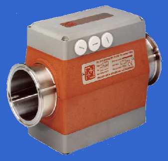
CONSTRUCTION
The
PD 340 flow transmitter consists of three parts: meter head, electronic
module, and terminal box. The electronic module and the terminal box are the
same for all sizes of transmitters.
The
Meter head consists
of a stainless metering pipe with clamp liners. Two magnet coils are mounted
external to the metering pipe. Inside the metering pipe two stainless
electrodes are mounted. The measuring section is designed so that changes in
flow profile do not affect meter accuracy hence the transmitter has a wide
range of flow rates within its linear accuracy. Changes from laminar to
turbulent flow do not affect the linear accuracy and changing viscosity has no
effect on meter accuracy. The calibration of the meter head is carried out
using a computer controlled calibration facility.
Fig.
1: Structure
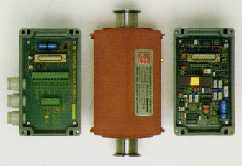
The
Electronic Module is
micro-processor based and both controls the sequence of measurement and output
signal transmission.
The use of the micro-processor has enabled a compact
design to be
achieved yet including many functions. The
electronic module is
available in two versions, standard and extended. The standard version has two
pulse outputs and can be
directly connected
to a display unit.
In the extended
version, one of the pulse outputs can be
changed into
analogue output, 4-20mA. Besides, it is
possible to connect
the transmitter to a data network for central processing.
The
Terminal Box is
completely separated from the electronic module. Hence connections can be
changed without disruption to the electronics. All terminals in the terminal
base are clearly marked with both number and
function. The box is
also equipped with 3 cable glands,
PG 11.
OPERATING
PRINCIPLES
The meterhead consists of a metering pipe with two magnetic coils. When a
current is applied to the coils a magnetic field is produced at right angles
to the metering pipe. With a conductive liquid flowing through the metering
pipe an electrical voltage is induced and measured by two electrodes mounted
in the metering pipe. This voltage is proportional to average velocity of flow
and therefore to the volume flowing. The micro-processor in the transmitter
controls the current generator keeping the magnetic field constant. The
voltage of the electrodes is taken via an amplifier and signal converter to
the micro-processor which calculates the liquid flow.
Specifications:
Deviation flow
measurement:-
Less than ±0.3%of max.
flow.
Deviation
current output: Cf. fig. 3,
plus ±0.3% of range
for current output.
Linearity:
See fig. 3.
Repeatability: Better than 0.5 x
deviation,
see fig. 3.
Ambient
temperature effect: Less
than0.04%/10°C.
Voltage
supply effect:
Less than 0.01%/10%.
Response
time:
0.2 sec. on pulse output, 1 sec on current output.
Max. capacity:
PD 340 – C 25: 8 m 3 /h.
C 38: 20 m 3 /h.
C 51: 40 m 3 /h.
C 63: 80 m 3 /h.
C 76: 120 m 3 /h.
Measurement of temperature:
Deviation: Less than ±0.9°C
with Pt-100 detector
Din 43760.
Limits:
From – 30°C to +100°C.
Ambient temperature:
From -10°C to + 50°C.
Power supply:
24 V AC ± 15%, 50/60 c/s or 24 V DC ± 15%.
Power consumption:
Max. 6 W.
Liquid:
Conductivity: Min. 5mS/cm.
Temperature:
From –30°C
to +100°C.
Pressure: Max. 10 bar.
Outputs: The transmitter can give two different output signals, pulse signal or current
signal
External
voltage supplies are required for both types of signals
Pulse
signals:
max 40V, 100mA
Current signal:
10 - 30 V
Material:
Electrodes: Stainless steel AISI 316.
Metering pipe: Stainless steel AISI 316.
Coating inside metering pipe: FEP Teflon
Housing:
PPO Noryle
Connections:
Clamp pipe coupling DS/ISO 2852.
Approvals.
Compliance with EMC-directive no.: 89/336/ECC
Generic standards for
emission: Residential,
commercial and light industry EN 50081-1
Industry EN 50081-2
Generic standards for
immunity: Residential, commercial and
light industry EN 50082-1
Industry EN 50082-2
Vibration
(sinusoidal):
IEC 68-2-6 Test Fc
LOCATION
OF TRANSMITTER
The transmitter should be located in the
piping system so that the metering pipe is always filled with liquid as the
transmitter can register flow even if the metering pipe
is empty. As the transmitter sees air in the liquid as a
volume, the volume of air in the liquid must be reduced to a minimum, and the
transmitter should be located in the piping system, at the point of maximum
pressure. Here the volume of the air is minimum hence the influence of air on
the measurement will also be minimum. If the transmitter is located downstream
of a pump which may suck air during the measuring period an air eliminator
should be mounted upstream of the transmitter.
The transmitter can be mounted both horizontally and
vertically. Air elimination must always be guaranteed. The positive flow
direction is indicated by an arrow on the
meterhead.
To create the best conditions for precise metering a straight run of at least
3x D should be mounted up- stream
and downstream of the transmitter. When selecting the
location of the transmitter it must be ensured that the ambient temperature is
kept within the specified limits. Finally, the transmitter should be located so
that the electronic box and the terminal box can be dismantled and mounted on
site. The transmitter should always be electrically connected thus preventing
condensation in the electronics.
OUTPUT
SIGNALS
The
transmitter has three outputs, OUTPUT 1, 2, and 3. OUTPUT 1 is a power supply
output, which can be used for power supply of external counter circuit. The
voltage of the output can vary from 20 to 32 V DC.
OUTPUT 2
can be selected for one of three functions:
- 1:
Pulse signal, 0-5 c/s. The signal is taken to a counter, electronic or
electromechanical, for indication of the total volume, e.g. in litres.
- 2:
Sign for OUTPUT 3. The signal indicates the flow direct- ion and can be
taken to an UP/DOWN counter, which is actuated by pulses from OUTPUT 3.
- 3:
The output signal from the pre-set counter. Before start of measuring a
SET-point via the display is inserted, and the pre-set counter is reset.
When the required volume is achieved, OUTPUT 2 gives a stop signal.
OUTPUT 3
can be selected for one of two functions:
- 1:
Pulse signal 0-1000 c/s. The signal can for instance be taken to a counter
for volume registration. The signal can also be used for registration of
actual flow.
- 2:
Current signal 4-20mA (only for transmitter in extended version). The signal
can be taken to a regulator for controlling the liquid flow. Besides these
three outputs it is possible to connect the flow transmitter direct to the
display unit PD 210. It is also possible to connect the extended version
transmitter to a communication system for data processing.
|